Superchargers
4
Less Procharger HO Intercooled
C5 Corvette Supercharger Installation
"Go
Here" to
see more of our installations.
|
The Mission:
To exceed 580 crankshaft HP
on a Stock C5 Corvette
"Go Here"
for Dyno Figures
The Car:
2003 Z06 Corvette
The Supercharger System:
Twin High Flow HO Intercooled Procharger®
The Installer:
Superchargers
4
Less
Elm Grove, Louisiana
|

If you have high speed internet service...
"Go Here"
to see and hear our Procharger P-1SC-1!
|
We hope that the following
photos, advise, tips and instructions will help anyone installing or
thinking about installing an ATI Procharger HO Intercooled system on a C5 Corvette.
If you have high speed
internet service,
"Go Here"
to see the installation manual that Procharger provided with our system.
|
1. System received and inspected.
Everything looks good and is accounted for.
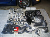
"Go here for a larger view"
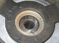
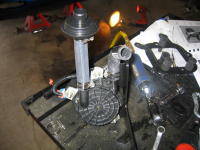
2. Pinning the harmonic balancer to the
Crankshaft. The harmonic balancer on the LS1 engine is not keyed to the
crankshaft, so it must be pinned to keep it from shifting with the added torque
load of the supercharger. ATI and Vortech both supply the tools to accomplish
this task.
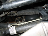
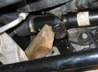
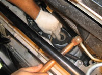
Getting to the area that we need to work on is not so easy though. On a C5
Corvette the steering rack sits directly in front of the crankshaft bolt that
retains the harmonic balancer.
We jacked up the car and removed both front wheels. With a 18mm socket on an air
impact wrench we removed the nuts that hold the tie rod ends to the spindles, no
problems so far. We unbolted the power steering cooler from the cross
member and tied it up and out of the way with a piece of wire. We then removed
the bolts holding the steering rack and the traction control unit. The traction
control unit was easily raised and tied out of the way. The steering rack would
not go up high enough to allow access to the crankshaft bolt. We pushed the rack
toward the driver side of the car (rotating the steering wheel to the right
seemed to help), we were then able to raise the passenger side
of the rack high enough to allow us to get a break over handle and 24mm socket
onto the bolt. We found that a piece of a 2 by 4 was perfect to hold the
steering rack up and out of the way.
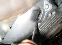
The bolt that holds the harmonic
balancer on, has a locking compound on it. The engine will spin while trying to
loosen the bolt. We stopped this from happening by sticking a screw driver
through one of the vent holes in the back of the bell housing and into the teeth
of the flywheel.
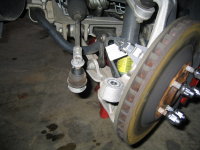
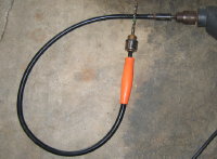
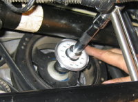
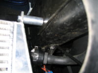
We removed the factory front bolt and
then installed the provided ATI drill guide/alignment tool onto the end of the
crankshaft. Clearance between the radiator and drilling area is very tight, so
we used a flexible drill attachment (see picture above) on our drill to give
us more room to work. We also wrapped our drill bit with tape at the
pre-measured depth that ATI recommended, to give us a stopping point for our drilling depth.
We checked the depth of the pin hole before we tapped the pin into place, it
would be a real problem if we tapped the pin into a hole that was a millimeter
to shallow.
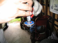
We cleaned the old thread locking
compound off of the original crankshaft bolt and reapplied LockTite® The
original bolt was then reinstalled, torqued to 40lbs and then turned
another 120 degrees.
3. Relocating the air pump was fairly
simple and is required to make room for the driver side intercooler. The
relocation moves the air pump further forward. We removed the front air dam and
panel behind it on the driver side of the car. The factory air pump assembly was
removed and modified as instructed in the owners manual. We reinstalled the
modified pump assembly onto the new ATI supplied bracket. Our set of
instructions called for rubber isolator bushings, which were not supplied. We
contacted ATI about the bushings and found out that they are no longer on the
packing list... cannot hear any noise, must be fine without them. (Tech support
was to make note of this discrepancy) The finished assembly mounted back onto
the car using two of the three original threaded bolt holes.
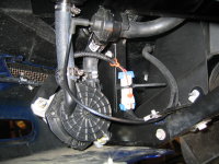
4. Relocation of the horns is required
on the passenger side to make room for the other intercooler. We straightened
out the tab that holds the horns in their original position and rotated them as
the manual instructed. This still did not give us the clearance we needed. We
had to rotate one of the horns on it's bracket and bend the bracket toward the
radiator to get the clearance required.
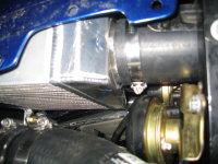
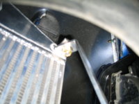
5. Mounting of the Intercoolers: The
intercoolers mount to the frame of the car with two bolts each. The ATI supplied
longer bolts, brackets and stand offs are shown above. We found that it was
easier to tighten the bolt in "fig 1" from above by opening the head lights and
reaching it from the top. The bracket to intercooler bolt "fig 2" was easier to
reach from the bottom.
"Click Here"
to
continue to page 2
Superchargers
4 Less
Call: 318-286-9169
If you find
it for less just give us a call...